-
Product Overview
-
Product Details
-
Data Download
-
Related Products
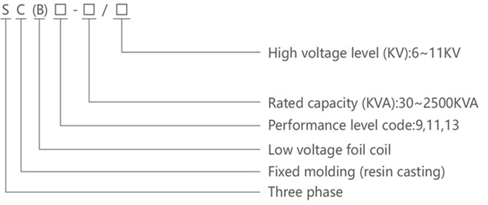
SC(B)9 Series Epoxy Resin Dry-type Transformer
The SC (B) series epoxy resin dry type transformers have the advantages of flame retardant, fireproof, explosion-proof, maintenance free, and small size due to their coils being encapsulated with epoxy resin. They can be directly installed in load centers and are widely used in power transmission and transformation systems, as important places as commercial residences, public buildings, airports, as well as in harsh environments like subways, smelters, ships, and marine drilling.
Standard: IEC60076-1, IEC60076-11.
Conatct Us
Product Details
Selection
Operating conditions
1. Ambient temperature: maximum temperature: +40°C, minimum temperature: -25℃ .
2. Average temperature of the hottest month:+30℃, average temperature in the hottest year:+20℃ .
3. Altitude not exceeding 1000m.
4. The waveform of the power supply voltage is similar to a sine wave.
5. The three-phase supply voltage should be approximately symmetrical.
6. The relative humidity of the surrounding air should be lower than 93%.
7. And there should be no water droplets on the surface of the coil
8. Where to use: indoors or outdoors.
Features
1. The carefully designed coil structure and vacuum immersion treatment ensure that the SG (B) 10 transformer operates without
partial discharge and will not exhibit crack performance throughout its service life. Its insulation level will remain in good condition as before.
2. The high-voltage part adopts continuous wire winding, low-voltage foil winding, vacuum immersion, curing treatment, and high-strength ceramic support, which has good resistance to sudden short circuit currents.
3. Flame retardant,explosion-proof, non-toxic, self-extinguishing, and fireproof
4. The SG (B) 10 transformer produces almost no smoke when burned in a high-temperature open flame
5. The insulation level of the transformer is Class H (180℃).
6. The insulation layer is very thin, with strong short-term overload capacity, without the need for forced cooling, and can overload by 120% for long term use, 140% lasting for 3 hours. Due to its elasticity and non aging properties, this insulation material can be fully loaded at one time at ± 50℃ .
Structure

■ Iron core:
The iron core is made of high-quality oriented cold-rolled silicon steel sheet, with a
laminated structure of 45° full oblique seam, and the core column is bound with insulating tape.
● The surface of the iron core is sealed with insulating resin paint to prevent moisture and rust, and the clamps and fasteners are surface-treated to prevent rust.
■ Low voltage copper foil coil:
● The low-voltage winding is wound with high-quality copper foil, so that zero axial short-circuit stress can be achieved in the case of short circuit. The interlayer and winding end are insulated with thermosetting epoxy prepreg cloth. The whole winding is placed in the oven. After heating, the winding is aggregated into a solid whole. Scientific and reasonable design and pouring process make the product partial discharge less, noise lower, and heat dissipation capacity strong.
■ High voltage winding:
● The high-voltage winding adopts enamelled copper wire or film-coated copper wire, and glass fiber and epoxy resin composite material are used for insulation. Its expansion coefficient is similar to that of copper conductor, and it has good impact resistance, temperature change resistance, and crack resistance. All components of glass fiber and epoxy resin are self-extinguishing, flame retardant and non-polluting. Epoxy resin has good insulation properties and is especially suitable for making high-voltage coils.
■ Temperature control device and air cooling system:
● The temperature control device has the functions of failure alarm, over-temperature alarm, over-temperature trip, automatic/manual start and stop of the fan, and is connected to the computer through the RS485 interface for centralized monitoring and control.At the same time, it also has the function of "black gate", which can record the winding temperature of the transformer when it is powered off.
● The air-cooling system adopts a cross-flow top-blowing cooling fan, which has the characteristics of low noise, high wind pressure, and beautiful appearance. It can run for a long time under the condition of forced air cooling at 125% of the rated load.
■ Shell:
● Protect the shell and provide further safety protection for the transformer,with protection levels such as IP20, IP23, etc.
● The shell materials include cold-rolled steel plate, stainless steel plate, aluminum alloy, etc. for users to choose from.

■ The factory configuration of SCB without protective shell (IP00) is as follows
● 4 bi-directional flat wheels (when requested by the customer)
● 4 lugs
● Towing holes on the base
● 2 grounding points
● 1 nameplate
● 2 "Electric Hazard" warning signs
● No load voltage regulating tap, operated when the transformer is powered off, to adapt the transformer to the actual supply voltage
● High voltage side connecting rod with connecting wire from above
● Low-voltage outgoing busbar with upward outlet
■ The factory configuration of SCB with IP21, IP23 metal protective shell is as follows
● All contents mentioned above for SCB without protective casing (Ip00)
● 1 set of IP21 metal protective housing, standard anti-corrosion protection
SCB9-30~2500/10KV technical data
| Rated capacity (KVA) |
Voltage combination | Connection group label | No-load loss(W) | Load Loss(w) 120℃ | No-load current (%) |
Short circuit impedance(%) | Dimensions | Total weight (kg) |
||||
| High voltage (KV) |
Tapping range | Low voltage (KV) |
L | W | H | |||||||
| 30 | 6 6.3 6.6 10 10.5 11 |
±5 ±2×2.5 |
0.4 | Dyn11 Yyn0 | 220 | 750 | 2.4 | 4 | 700 | 350 | 620 | 250 |
| 50 | 310 | 1060 | 2.4 | 710 | 350 | 635 | 295 | |||||
| 80 | 420 | 1460 | 1.8 | 860 | 730 | 780 | 430 | |||||
| 100 | 450 | 1670 | 1.8 | 940 | 710 | 795 | 520 | |||||
| 125 | 530 | 1960 | 1.6 | 1000 | 710 | 860 | 670 | |||||
| 160 | 610 | 2250 | 1.6 | 1080 | 710 | 1020 | 840 | |||||
| 200 | 700 | 2680 | 1.4 | 1100 | 710 | 1060 | 960 | |||||
| 250 | 810 | 2920 | 1.4 | 1150 | 710 | 1100 | 1120 | |||||
| 315 | 990 | 3670 | 1.2 | 1150 | 770 | 1125 | 1230 | |||||
| 400 | 1100 | 4220 | 1.2 | 1190 | 870 | 1175 | 1485 | |||||
| 500 | 1310 | 5170 | 1.2 | 1230 | 870 | 1265 | 1580 | |||||
| 630 | 1510 | 6220 | 1 | 1465 | 870 | 1245 | 1840 | |||||
| 630 | 1460 | 6310 | 1 | 6 | 1465 | 870 | 1245 | 1840 | ||||
| 800 | 1710 | 7360 | 1 | 1420 | 870 | 1395 | 2135 | |||||
| 1000 | 1990 | 8610 | 1 | 1460 | 870 | 1420 | 2500 | |||||
| 1250 | 2350 | 10260 | 1 | 1580 | 970 | 1485 | 2970 | |||||
| 1600 | 2760 | 12400 | 1 | 1640 | 1120 | 1715 | 3900 | |||||
| 2000 | 3400 | 15300 | 0.8 | 1780 | 1120 | 1710 | 4225 | |||||
| 2500 | 4000 | 18180 | 0.8 | 1850 | 1120 | 1770 | 4790 | |||||
Overall and mounting dimensions(mm)
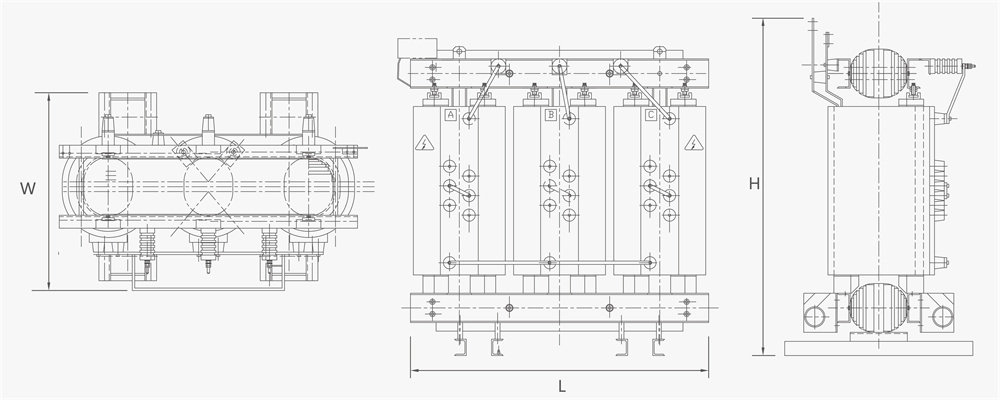
Note: The dimensions and weights provided are only for reference in design and selection.
The final size and weight are subject to our prodect drawings.
SCB10-30~2500/10KV technical data
| Rated capacity (KVA) |
Voltage combination | Connection group label | No-load loss(W) | Load Loss(w) 120℃ | No-load current (%) |
Short circuit impedance(%) | Dimensions | Total weight (kg) |
||||
| High voltage (KV) |
Tapping range | Low voltage (KV) |
L | W | H | |||||||
| 30 | 6 6.3 6.6 10 10.5 11 |
±5 ±2×2.5 |
0.4 | Dyn11 Yyn0 | 190 | 710 | 2 | 4 | 580 | 450 | 650 | 300 |
| 50 | 270 | 1000 | 2 | 600 | 450 | 650 | 380 | |||||
| 80 | 370 | 1380 | 1.5 | 880 | 500 | 800 | 470 | |||||
| 100 | 400 | 1570 | 1.5 | 970 | 500 | 820 | 560 | |||||
| 125 | 470 | 1850 | 1.3 | 970 | 500 | 860 | 650 | |||||
| 160 | 540 | 2130 | 1.3 | 980 | 650 | 950 | 780 | |||||
| 200 | 620 | 2530 | 1.1 | 1000 | 650 | 970 | 880 | |||||
| 250 | 720 | 2760 | 1.1 | 1040 | 760 | 1070 | 1030 | |||||
| 315 | 880 | 3470 | 1 | 1100 | 760 | 1110 | 1250 | |||||
| 400 | 980 | 3990 | 1 | 1170 | 760 | 1235 | 1400 | |||||
| 500 | 1160 | 4880 | 1 | 1190 | 760 | 1250 | 1600 | |||||
| 630 | 1340 | 5880 | 0.85 | 1220 | 760 | 1250 | 1900 | |||||
| 630 | 1300 | 5960 | 0.85 | 6 | 1220 | 760 | 1250 | 1900 | ||||
| 800 | 1520 | 6960 | 0.85 | 1330 | 760 | 1330 | 2580 | |||||
| 1000 | 1770 | 8130 | 0.85 | 1350 | 920 | 1450 | 2850 | |||||
| 1250 | 2090 | 9690 | 0.85 | 1440 | 920 | 1550 | 3200 | |||||
| 1600 | 2450 | 11700 | 0.85 | 1510 | 1170 | 1620 | 3800 | |||||
| 2000 | 3060 | 14400 | 0.7 | 1530 | 1170 | 1785 | 4280 | |||||
| 2500 | 3600 | 17100 | 0.7 | 1560 | 1170 | 1930 | 5250 | |||||
Overall and mounting dimensions(mm)
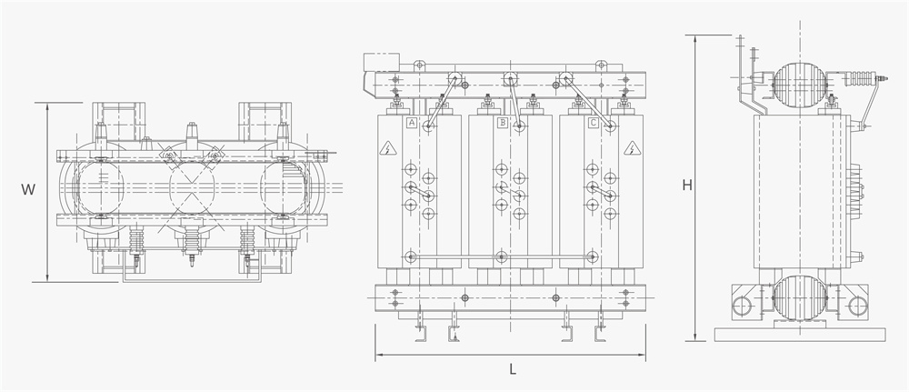
Note: The dimensions and weights provided are only for reference in design and selection.
The final size and weight are subject to our prodect drawings.
SCB11-30~2500/10KV technical data
| Rated capacity (KVA) |
Voltage combination | Connection group label | No-load loss(W) | Load Loss(w) 120℃ | No-load current (%) |
Short circuit impedance(%) | Dimensions | Total weight (kg) |
||||
| High voltage (KV) |
Tapping range | Low voltage (KV) |
L | W | H | |||||||
| 30 | 6 6.3 6.6 10 10.5 11 |
±5 ±2×2.5 |
0.4 | Dyn11 Yyn0 | 170 | 710 | 2.3 | 4 | 955 | 750 | 840 | 270 |
| 50 | 240 | 1000 | 2.2 | 970 | 750 | 860 | 340 | |||||
| 80 | 330 | 1380 | 1.7 | 1015 | 750 | 925 | 460 | |||||
| 100 | 360 | 1570 | 1.7 | 1030 | 750 | 960 | 530 | |||||
| 125 | 420 | 1850 | 1.5 | 1060 | 750 | 1000 | 605 | |||||
| 160 | 480 | 2130 | 1.5 | 1090 | 900 | 1045 | 730 | |||||
| 200 | 550 | 2530 | 1.3 | 1105 | 900 | 1080 | 825 | |||||
| 250 | 640 | 2760 | 1.3 | 1180 | 900 | 1125 | 1010 | |||||
| 315 | 790 | 3470 | 1.1 | 1225 | 900 | 1140 | 1165 | |||||
| 400 | 880 | 3990 | 1.1 | 1330 | 900 | 1195 | 1490 | |||||
| 500 | 1040 | 4880 | 1.1 | 1345 | 900 | 1255 | 1650 | |||||
| 630 | 1200 | 5880 | 0.9 | 1540 | 1150 | 1175 | 1915 | |||||
| 630 | 1170 | 5960 | 0.9 | 6 | 1540 | 1150 | 1175 | 1915 | ||||
| 800 | 1360 | 6960 | 0.9 | 1600 | 1150 | 1220 | 2305 | |||||
| 1000 | 1590 | 8130 | 0.9 | 1645 | 1150 | 1285 | 2690 | |||||
| 1250 | 1880 | 9690 | 0.9 | 1705 | 1150 | 1345 | 3225 | |||||
| 1600 | 2200 | 11700 | 0.9 | 1765 | 1150 | 1405 | 3805 | |||||
| 2000 | 2740 | 14400 | 0.7 | 1840 | 1150 | 1475 | 4435 | |||||
| 2500 | 3240 | 17100 | 0.7 | 1900 | 1150 | 1560 | 5300 | |||||
| 1600 | 2200 | 12900 | 0.9 | 8 | 1765 | 1150 | 1405 | 3805 | ||||
| 2000 | 2740 | 15900 | 0.7 | 1840 | 1150 | 1475 | 4435 | |||||
| 2500 | 3240 | 18800 | 0.7 | 1900 | 1150 | 1560 | 5300 | |||||
Overall and mounting dimensions(mm)
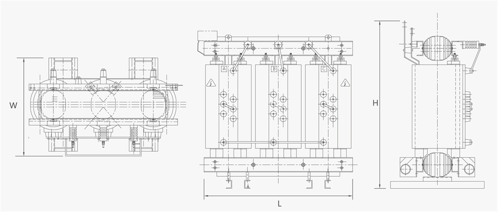
Note: The dimensions and weights provided are only for reference in design and selection.
The final size and weight are subject to our prodect drawings.
SCB12-30~2500/10KV technical data
| Rated capacity (KVA) |
Voltage combination | Connection group label | No-load loss(W) | Load Loss(w) 120℃ | No-load current (%) |
Short circuit impedance(%) | Dimensions | Total weight (kg) |
||||
| High voltage (KV) |
Tapping range | Low voltage (KV) |
L | W | H | |||||||
| 30 | 6 6.3 6.6 10 10.5 11 |
±5 ±2×2.5 |
0.4 | Dyn11 Yyn0 | 150 | 710 | 2.3 | 4 | 955 | 750 | 840 | 270 |
| 50 | 215 | 1000 | 2.2 | 970 | 750 | 860 | 340 | |||||
| 80 | 295 | 1380 | 1.7 | 1015 | 750 | 925 | 460 | |||||
| 100 | 320 | 1570 | 1.7 | 1030 | 750 | 960 | 530 | |||||
| 125 | 375 | 1850 | 1.5 | 1060 | 750 | 1000 | 605 | |||||
| 160 | 430 | 2130 | 1.5 | 1090 | 900 | 1045 | 730 | |||||
| 200 | 495 | 2530 | 1.3 | 1105 | 900 | 1080 | 825 | |||||
| 250 | 575 | 2760 | 1.3 | 1180 | 900 | 1125 | 1010 | |||||
| 315 | 705 | 3470 | 1.1 | 1225 | 900 | 1140 | 1165 | |||||
| 400 | 785 | 3990 | 1.1 | 1330 | 900 | 1195 | 1490 | |||||
| 500 | 930 | 4880 | 1.1 | 1345 | 900 | 1255 | 1650 | |||||
| 630 | 1070 | 5880 | 0.9 | 1540 | 1150 | 1175 | 1915 | |||||
| 630 | 1040 | 5960 | 0.9 | 6 | 1540 | 1150 | 1175 | 1915 | ||||
| 800 | 1210 | 6960 | 0.9 | 1600 | 1150 | 1220 | 2305 | |||||
| 1000 | 1410 | 8130 | 0.9 | 1645 | 1150 | 1285 | 2690 | |||||
| 1250 | 1670 | 9690 | 0.9 | 1705 | 1150 | 1345 | 3225 | |||||
| 1600 | 1960 | 11700 | 0.9 | 1765 | 1150 | 1405 | 3805 | |||||
| 2000 | 2440 | 14400 | 0.7 | 1840 | 1150 | 1475 | 4435 | |||||
| 2500 | 2880 | 17100 | 0.7 | 1900 | 1150 | 1560 | 5300 | |||||
| 1600 | 1960 | 12900 | 0.9 | 8 | 1765 | 1150 | 1405 | 3805 | ||||
| 2000 | 2440 | 15900 | 0.7 | 1840 | 1150 | 1475 | 4435 | |||||
| 2500 | 2880 | 18800 | 0.7 | 1900 | 1150 | 1560 | 5300 | |||||
Overall and mounting dimensions(mm)
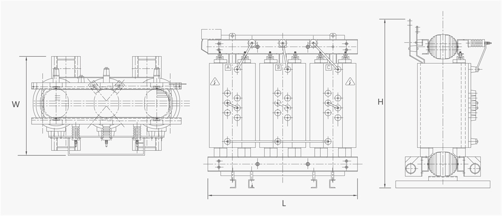
Note: The dimensions and weights provided are only for reference in design and selection.
The final size and weight are subject to our prodect drawings.
SCB13-30~2500/10KV technical data
| Rated capacity (KVA) |
Voltage combination | Connection group label | No-load loss(W) | Load Loss(w) 120℃ | No-load current (%) |
Short circuit impedance(%) | Dimensions | Total weight (kg) |
||||
| High voltage (KV) |
Tapping range | Low voltage (KV) |
L | W | H | |||||||
| 30 | 6 6.3 6.6 10 10.5 11 |
±5 ±2×2.5 |
0.4 | Dyn11 Yyn0 | 135 | 640 | 2.3 | 4 | 955 | 750 | 840 | 270 |
| 50 | 195 | 900 | 2.2 | 970 | 750 | 860 | 340 | |||||
| 80 | 265 | 1240 | 1.7 | 1015 | 750 | 925 | 460 | |||||
| 100 | 290 | 1410 | 1.7 | 1060 | 750 | 960 | 560 | |||||
| 125 | 340 | 1660 | 1.5 | 1075 | 750 | 1000 | 630 | |||||
| 160 | 385 | 1910 | 1.5 | 1105 | 900 | 1045 | 770 | |||||
| 200 | 445 | 2270 | 1.3 | 1120 | 900 | 1105 | 875 | |||||
| 250 | 515 | 2480 | 1.3 | 1195 | 900 | 1125 | 1055 | |||||
| 315 | 635 | 3120 | 1.1 | 1555 | 1150 | 1175 | 1190 | |||||
| 400 | 705 | 3590 | 1.1 | 1225 | 900 | 1140 | 1500 | |||||
| 500 | 835 | 4390 | 1.1 | 1315 | 900 | 1190 | 1700 | |||||
| 630 | 965 | 5290 | 0.9 | 1345 | 900 | 1265 | 1985 | |||||
| 630 | 935 | 5360 | 0.9 | 6 | 1555 | 1150 | 1175 | 1985 | ||||
| 800 | 1090 | 6260 | 0.9 | 1600 | 1150 | 1220 | 2360 | |||||
| 1000 | 1270 | 7310 | 0.9 | 1660 | 1150 | 1285 | 2775 | |||||
| 1250 | 1500 | 8720 | 0.9 | 1720 | 1150 | 1350 | 3310 | |||||
| 1600 | 1760 | 10500 | 0.9 | 1780 | 1150 | 1405 | 3940 | |||||
| 2000 | 2190 | 13000 | 0.7 | 1840 | 1150 | 1475 | 4595 | |||||
| 2500 | 2590 | 15400 | 0.7 | 1900 | 1150 | 1565 | 5495 | |||||
| 1600 | 1760 | 11600 | 0.9 | 8 | 1780 | 1150 | 1405 | 3940 | ||||
| 2000 | 2190 | 14300 | 0.7 | 1840 | 1150 | 1475 | 4595 | |||||
| 2500 | 2590 | 17000 | 0.7 | 1900 | 1150 | 1565 | 5495 | |||||
Overall and mounting dimensions(mm)
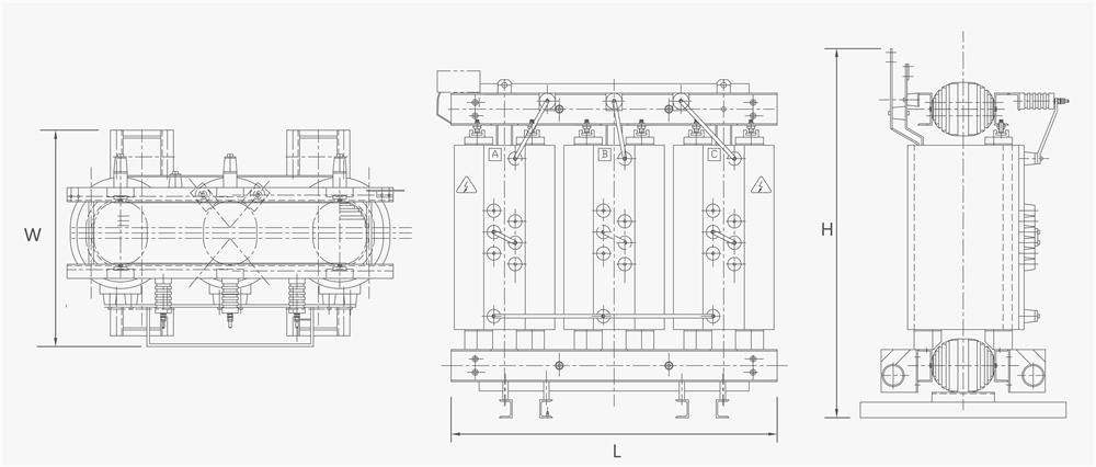
Note:The dimensions and weights provided are only for reference in design and selection.
The final size and weight are subject to our prodect drawings.
Carry
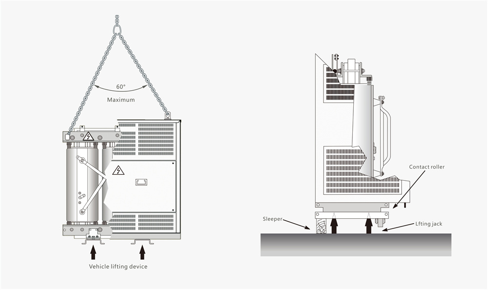
● The transformer is equipped with safe handling devices.
● For transformers without enclosures and transformers with top door openings, use the four lifting lugs of the transformer for lifting (must be lifted vertically, not diagonally); For transformers with 2 lifting lugs in the center of the top of the casing, use 2 lifting lugs for lifting. The angle formed by the sling should not exceed 60° .
● Firstly, the forking capacity of the forklift should be checked. If appropriate, the fork arm should be inserted into the base channel steel after removing the rollers.
● Pulling and moving the transformer should be carried out from the base. For this purpose, holes with a diameter of 27 mm are made on each side of the base. Dragging is possible in two directions: the axis of the base and the direction perpendicular to this axis.
 CNC ELECTRIC GROUP ZHEJIANG TECHNOLOGY CO.,LTD
 Products
 Projects
 Solutions
 Service
 News
News About CNC
 Contact Us


