-
Product Overview
-
Product Details
-
Data Download
-
Related Products
XGN15-12~24 Air-insulated RMU(Fixed Type)
Rating:
Rated voltage 12/24KV, rated current reach to 630A. Application:
mainly applicable in urban power grid features and renovation project, industrial and mining enterprises, high-rise buildings and communal facilities .For power distribution, controlling and protection on electric equipment as the loop power supply unit or
terminal equipment. It also can be installed in pre-loaded substation
Feature:
Use SF6 load switch and load switch-fuse combination as main switch. Equipped with vacuum load switch and spring operating mechanism which can be operated by hand or electric. Grounding switch and insulating switch are equipped with hand operating mechanism, with small volume and high security.
Standard: IEC60420
Conatct Us
Product Details
Selection
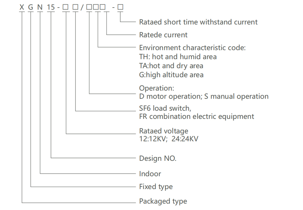
Operating conditions
1. Ambient air temperature: -15℃ ~+40℃ .Daily average temperature:≤35℃ .
2. Altitude: ≤1000m.
3. Relative humidity : Daily average≤95% ,daily averange of vapour pressure≤2.2kpa Monthly average≤90%,monthly averange of vapour pressure≤1.8kpa.
4. Earthquake intensity: ≤magnitude 8.
5. Applicable in the places without corrosive and flammable gas. Note: Customized products are available.
Features
1. Modular design, where each unit module can be combined and expanded arbitrarily, facilitating flexible system configurations and wide adaptability.
2. The cabinet adopts armored structure with metal partitions between compartments.
3. The operating mechanism adopts corrosion-resistant metals, and the rotating parts are designed with self-lubricating bearings, ensuring unaffected performance in various environments and eliminating the need for regular maintenance.
4. To accommodate power grid automation and improve distribution reliability, it can be equipped with motorized mechanisms, distribution network control terminal units, and possesses telecontrol functions.
5. The compact design of the cabinet incorporates a three-position rotary load switch, effectively reducing the number of components and enabling mechanical interlocking for five protection measures.
6. The primary circuit simulation single-line diagram and analog display can demonstrate the internal status of the switch, enabling easy, accurate, and safe operation.
Technical data
| Rated voltage | Unit | 12KV | 24KV | ||||
| Item | / | Load switch cabinet | Combined
electrical cabinet |
Circuit breaker cabinet | 20KVSF6
Ring switch equipment |
||
| Rated frequency | HZ | 50/60 | 50/60 | 50/60 | 50/60 | ||
| Rated current | A | / | |||||
| Main busbar | A | 630 | 630 | 630 | 630 | ||
| Branch busbar | A | 630 | 125① | 630 | 630/≤100② | ||
| Rated insulation level | KV | / | |||||
| Power frequency withstand voltage | Phase-to-phase and phase-to-ground | KV | 42 | 42 | 42 | 65 | |
| Gap between breaks | KV | 48 | 48 | 48 | / | ||
| Break control and auxiliary circuit | KV | 2 | 2 | 2 | / | ||
| Lightning impulse withstand voltage | Phase-to-phase and phase-to-ground | KV | 75 | 75 | 75 | 85 | |
| Gap between breaks | KV | 85 | 85 | 85 | / | ||
| Rated short-time withstand current | KA | / | |||||
| Main circuit | KA | 20/3s | - | 25/2s | / | ||
| Grounding circuit | KA | 20/25 | - | 25/2s | / | ||
| Rated peak withstand current | KA | 50 | - | 63 | / | ||
| Rated short-circuit making current | KA | 50 | 80 | 63 | 50 | ||
| Rated short-circuit breaking current | KA | - | 31.5 | 25 | 31.5 | ||
| Rated transfer current | A | - | 1750 | - | 870 | ||
| Rated active load breaking current | A | 630 | - | - | 630 | ||
| Rated closed loop breaking current | A | 630 | - | 630 | / | ||
| Rated cable charging breaking cable | A | 10 | - | 15 | 25 | ||
| Protection degree | / | IP3X | IP3X | IP3X | / | ||
| Mechanical life | Load switch | times | 5000 | 5000 | 10000 | 3000 | |
| Grounding switch | times | 2000 | 2000 | 2000 | 2000 | ||
Notes:① up to the fuse rated current
② ≤100(Load switch-Fuse combination cabinet)
Structure
● Busbar room
1. The busbar room is arranged at the upper part of the cabinet.
In the busbar room, the main busbar is connected together and runs through
2. the entire row of switchgear
● Load switch
1. There is a three position load switch installed in the switch room. The shell of the load switch is made of epoxy resin cast columns, and filled with sulfur hexafluoride (SF6) gas as the insulation medium. SF6 gas density meters or gas density meters with alarm contacts can be installed in the switch room according to customer requirements
● Cable room
1. The load switch has a spacious cable room, mainly used for cable connections
2. with sufficient space also to install lightning arresters, current transformers, lower grounding switches and other components
Operating mechanism, interlock mechanism and low voltage control room
3. The low-voltage room with interlocking functions as a control panel also
4. Spring operating mechanism and mechanical interlocking device with position indicator installed in low-voltage room
5. The low-voltage room can also be equipped with auxiliary contacts, trip coils, emergency trip mechanisms, capacitive live displays, keylocks, and electric
6. operating devices
7. The low-voltage room space can also be used to install control circuits, metering instruments and protective relay
8. The 750mm wide cabinet has two identical low-voltage chambers, which can hold more accessories.
The whole XGN15 switchgear can be divided into upper and lower parts. The upper part of the cabinet includes busbar room, load switch, operating mechanism and low-voltage room, which is separated from the lower part of the cable room. Therefore, it is safer and easier to repair and modify the equipment installed in the upper unit, and to replace the whole upper unit.

Phase plan
| Phase plan number | DC01 | DC08 | DC01 | DC07 | DC04 |
| main bus-bar TMY |  |
 |
 |
 |
 |
| XGN15-12/24 Disposable
system diagram |
|||||
| Configuration | Incoming cabinet | Outgoing cabinet | Outgoing cabinet | Configuration | Measuring cabinet |
| Load switch FLN□-□D | 1 | 1 | 1 | 1 | 1 |
| Load switch FLRN□-□D | / | 1 | / | / | 2 |
| Charged
displayDXN-T/Q |
1 | / | 1 | 1 | 3 |
| Current Transformer LZZBJ9-□ | / | / | / | / | 2 |
| Voltage transformer JDZ-□ | / | 3 | / | / | / |
| Lightning arrester HY5WS | 3 | / | 3 | 3 | 2 |
| Fuse XRNT-□/□A | / | 3 | / | / | / |
| Meter | / | / | / | / | / |
| Protection method | / | / | / | / | / |
| Auxiliary functions | / | / | / | / | / |
| Operation mode | Manual operation | Manual operation | Manual operation | Manual operation | / |
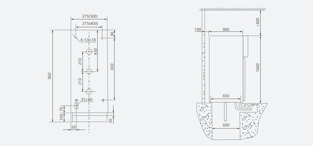
XGN15-24 Overall and mounting dimensions(mm)
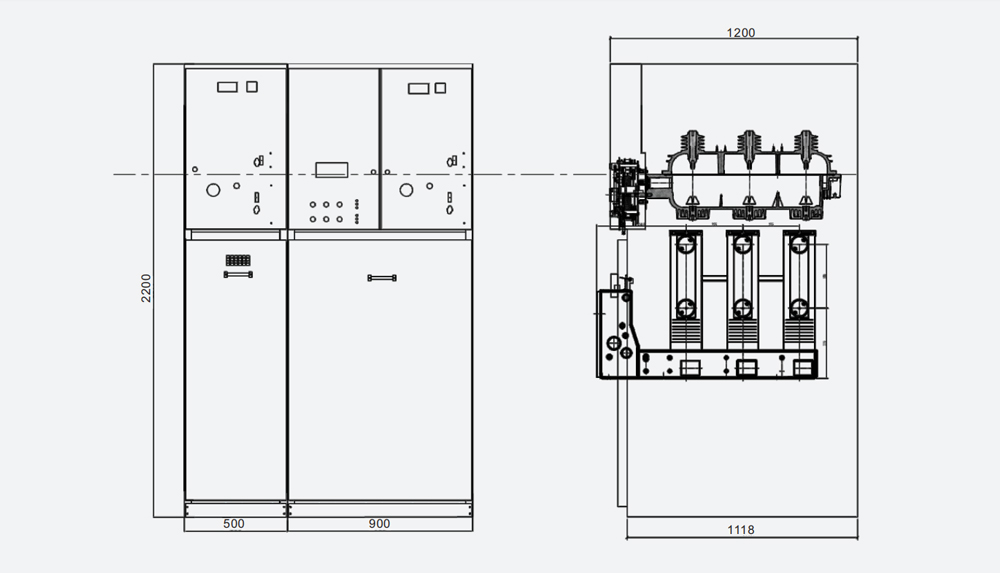
XGN15-12 Overall and mounting dimensions(mm)
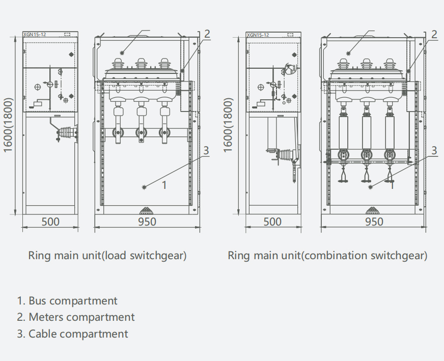
Schematic diagram of foundation
Switchgear diagrammatic sketch
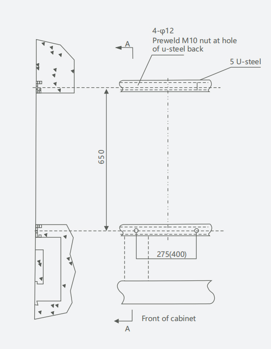
Switchgear installation Overall and mounting dimensions(mm) Cable incoming and outgoing configuration
Ordering information
1. Main circuit diagram, busbar diagram for main circuit, allocation diagram.
2. Switchgear outline size.
3. spare parts and their quantity.
4. Customized products are available per your requirements.
 CNC ELECTRIC GROUP ZHEJIANG TECHNOLOGY CO.,LTD
 Products
 Projects
 Solutions
 Service
 News
News About CNC
 Contact Us


